


Introduction to Elemental & Isotopic Analysis
A dust storm charges across the Sahara desert, whipping up sand and blowing it west, toward the ocean. Meanwhile, in the middle of the Atlantic Ocean, a team of scientists use filters to collect dust particles from the air, in hopes of identifying which elements are being transported across the Atlantic, from a desert thousands of miles away. These scientists will use ICP (inductively coupled plasma) technology to study the elemental composition of the dust.
Every object on earth is made of elements, from the sand in the Sahara to the snow in the Antarctic. In fact, all ordinary matter in the universe is made up of elements. Some elements will sound very familiar, such as helium, which is used to fill balloons, or sodium and chloride (aka salt), which you add to your food. Others may be a bit more obscure, such as praseodymium (used to create aircraft engines) or ruthenium (used to make jewelry). The word “element” is a term used to refer to a group of atoms that share the same defining characteristic, the number of protons in the nucleus. If two atoms have the same number of protons, but different number of neutrons, these atoms are referred to as isotopes of an element. In other words, all atoms of the element gold contain exactly 79 protons in the nucleus, however there are 19 different isotopes of gold, with the number of neutrons ranging from 90 to 126.
ICP-OES
Atomic Emission Spectroscopy (AES) is also known as Optical Emission Spectroscopy (OES) and is an elemental analysis technique wherein elements in a mixture are identified and quantified by observing the interactions of atoms with electromagnetic radiation (e.g. light). In OES a sample is ionized, at which time electrons are excited. Upon relaxation of the excited species, energy is emitted in the form of light. The wavelength of this light is measured by a detector.
OES is based on two important principles guiding the behavior of atoms. The first principle is that atoms can only exist in discrete states, also known as levels, which are characterized by distinct amounts of energy (this is referred to as quantized energy). One way to think about this is by comparing it to living in a two-story building. Your home may be on the ground floor, or it may be on the second floor, and you can live on either floor, but you cannot live in the space between. This is the same principle for atoms, and when the atom changes from one level to the next, it can either absorb or emit a photon (def.: a photon is a small packet of energy that can carry electromagnetic radiation) with energy that is equivalent to the difference in energy between the two levels. The second principle is that the frequency, ν, or wavelength, λ, of the radiation emitted or absorbed as the atom transitions from one energy level to the next is defined by the equation:
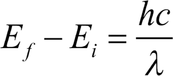
where E represents the energy of the atom at its initial ( i ) and final ( f ) state, h and c are constants, and λ represents the wavelength of the photon released. In other words, the greater the amount energy released, the shorter the wavelength of the electromagnetic radiation.
Tying these two principles together, we can see that at low temperatures the atoms of a sample of matter are essentially at their most relaxed levels, known as ground state, but these atoms can be excited to a higher energy level with heat from a flame, a plasma, or an electric arc or spark. When the atom relaxes from the excited energy level to a lower energy level, energy is released in the form of electromagnetic radiation and the wavelength of that light is inversely related to the difference in energy.
In an OES, atoms are excited in the inductively couple plasma and upon relaxation, photons are emitted. The emitted electromagnetic radiation then passes through an optical spectrometer where each wavelength is separated in space (this is the same process by which a prism separates white light into the various, distinct wavelengths and produces rainbows). The wavelengths emitted are characteristic of the atoms present, much like fingerprints. In this way, OES is used qualitatively to identify the atoms present in a sample. The intensity of the radiation can also be quantified to infer the concentration of each element.
A major component of the ICP-OES is the inductively coupled plasma. One of the first steps in ICP-OES is the introduction of sample into the plasma where it is atomized. Plasma is considered a fourth state of matter, distinct from gas, solid and liquid phases. To better understand the properties of plasma, it is useful to compare it to the other states of matter.
All matter exists in various states. In a solid, atoms are tightly and orderly arranged. When energy is added to an element in the solid state, the solid changes phase and becomes a liquid. In a liquid, the atoms adhere to a definite volume, but do not possess a fixed shape. As more energy is applied to the system, the liquid will transform into a gas. Gasses do not possess a fixed volume or shape. The atoms in the gaseous phase move about freely. When sufficient energy is applied to a gas, the atoms gain enough energy to cause an electron to detach from the nuclei. This produces a gaseous cloud consisting of positively charged ions (cations) and electrons. This final phase is identified as plasma.
An argon plasma is utilized for ICP-OES. Here, the argon ions maintain temperatures as great as 10,000 K. The energy of the plasma is capable of atomization (the conversion of a sample into atoms) and excitation of the atoms. Upon excitation, an electron from each atom transitions from the ground state to a state of higher energy. An atom in the excited state is not stable and will decay back to a less excited state. As the atom decays back to a less excited state, energy is lost by the emission of a photon. The magnitude of the photon’s energy is equivalent to the amount of energy initially required to excite the atom.
Because every element has a unique and characteristic set of energy levels, the wavelengths produced by the atoms can be used for identification purposes. In OES, a sample is introduced into the plasma where the sample is atomized and the atoms are excited. The emitted wavelengths are then analyzed with a detector for qualitative determination and the intensity of the wavelength is compared to that of standards of known concentration to determine the concentration of elements in the sample.
Several types of interference occur in ICP-OES, and these can be broadly divided into non-spectral and spectral interferences. A major non-spectral interference in ICP-OES is due to easily ionizable elements, particularly group I and group II elements . In ICP-OES the goal is to provide sufficient energy to excite an electron. If more energy is supplied, however, the electron may be completely dislodged, resulting in a cation. As there is no emission of electromagnetic radiation during this process, each atom that is ionized is lost from detection. The net result is a decrease in the intensity of emission lines for that element, resulting in an observed concentration lower than actual. Another major type of non-spectral interference occurs when there is a shift in the equilibrium of the system. This equilibrium exists between the ground state atoms, excited atoms, and ions. The overabundance of an element may shift this equilibrium, affecting the intensity of emission. For example, an overabundance of potassium (K) may cause a reduction in the apparent concentration of sodium (Na). The large number of K atoms may collide with the Na atoms, resulting in an increased signal when compared to a standard solution with a considerably lower concentration of K atoms.
The two types of spectral interferences that occur in ICP-OES are background emission interferences and the overlap of lines emitted from other elements. Background emission results from the emission of excited molecules in the plasma. Molecules that are formed during the rearrangement of atoms in the plasma can absorb energy and emit light. However, unlike the discrete bands emitted from atoms, broad bands are produced when molecules emit light. The broad bands may then overlap with lines of interest. The best method for dealing with this interference is to analyze a reagent blank and subtract the signal of interferences from the sample.
The other major source of spectral interference occurs when another element in the sample matrix emits light at a similar wavelength as the element of interest. In this case, identification and quantification are not possible. One workaround is to select a different emission wavelength, one that lacks interference.
ICP-MS
ICP-MS is an analytical technique that enables multi-element analysis of trace elements. This method is optimal for sub-part-per-million analysis, with ideal elemental concentrations ranging in the hundreds part-per-billion (ppb) to parts-per-trillion range. The major components of an ICP-MS are: the sample introduction system and ionization source, an interface for transferring analytes from a high-temperature and atmospheric pressure system to a low-temperature vacuum, a mass filter (called a mass analyzer), and ultimately a detector. The basic principle of ICP-MS involves the introduction of a sample into an inductively coupled plasma—where temperatures range from 6,000 to 10,000 K (that’s as hot as the surface of our sun!). When the sample is introduced into the plasma, molecules are broken down into gaseous atoms that are then ionized into, predominately, cations (ions with a positive charge). The ions are then transferred into an interface region designed to put the ions under vacuum. The interface region in an ICP-MS consists of two (or more) metal cone-shaped disks with a single hole in the center of each. The small diameter of the hole allows for sampling of ions concentrated at the center of the plasma—herein lies one of the limitations of ICP-MS as the small diameter of the cones inherently requires samples to be free of particulates, which may not be completely atomized and further ionized, that can clog the cones. Once the ions have traversed the interface, electrostatic lenses then focus the ions from the plasma source into a small beam. Because most ions formed in the plasma have a positive charge and therefore will be repelled by an electrostatic field of the same polarity (i.e. positive charge), the electrostatic lenses (small, positively charged tubes through which the ions traverse) collimate the ions into a narrow, focused beam. The ion beam is focused into the entrance of the mass spectrometer where the ions are then separated by their mass-to-charge ratio (m/z). The majority of ions produced in the plasma are singly charged (i.e. +1), so the m/z is effectively equivalent to the mass of each ion. In other words, a copper-63 (63Cu+) atom will be ionized to 63Cu + ; the mass (63) to charge (1) ratio is then 63. Ions with a m/z of 63 will be separated from other ions with a differing mass in the mass analyzer. Once separated, the ions with a defined mass are directed to a detector where they are counted.
There are several different mass analyzer techniques, each with its own method for separating ions. One of the most popular techniques in ICP-MS technology is the quadrupole mass spectrometer. The quadrupole mass analyzer works by filtering out everything except ions with a specific m/z. This is achieved by employing electrostatic forces of attraction and repulsion as well as inertia. The electrostatic forces at play in the quadrupole are explained by Coulomb’s law, which tells us that particles with a different charge attract and particles with the same charge repel. The tendencies of the particles to react to the attractive or repulsive forces, however, are also governed by inertia. The laws of inertia dictate that the more massive and object, the greater its tendency to resist changes in its state of motion. Arranging 4 rods in a diamond-like orientation with a space in the middle creates the electrostatic field of the quadrupole. Each rod is paired with a rod to its diametric opposite. One rod-pair has positive direct current (DC) and an alternating current (AC) potential applied to the rods, while the other rod-pair has a negative DC as well as an AC potential applied. The magnitude of the AC and DC voltages controls the trajectory of ions as they travel through the quadrupoles, allowing only ions with a specific mass/z through to the detector at any given time.
To better understand the theory behind the quadrupole, envision the rods aligned along a Cartesian coordinate, where one rod-pair is aligned along the x-axis and the other is aligned along the y-axis. Imagine the rod-pair in the x-direction have a positive DC and AC voltage applied, while the rod-pair in the y-direction have a negative DC and an AC voltage applied. Because lighter ions are more readily affected by electrostatic variations, these ions will readily respond to changes in alternating current. When the alternating current on a rod-pair is positive, the rods will repel these smaller cations. When the AC is negative, the rods will attract the smaller cations. If the cations make contact with the rods, they will be neutralized and disposed from the system. At a given AC voltage, then, all cations with a mass less than the mass of interest will have an unstable trajectory and will not be detected.
Meanwhile, the more massive cations, with greater inertia, will resist the forces resulting from the AC potential. Now consider that each rod-pair has a DC potential of opposite sign. Suppose the rod-pair in the x-direction has a positive DC potential and the rod-pair in the y-direction has a negative DC potential. The positive DC potential will focus the cations towards the center of the rods, but the negative DC potential will attract the more massive ions, and any cation with a mass greater than the mass of interest will collide with the negative DC rod pair. With these factors (AC and DC potentials) combined, the quadrupole selectively allows cations with a single m/z through the mass filter. The magnitudes of the AC and DC potentials are adjusted to allow ions to be detected sequentially. At this point, the ions are converted to an electronic signal at the detector and measured.
Because quadrupoles have low resolution and filter ions based on m/z, distinct species with similar m/z will not be distinguishable. This leads to interferences during analysis. There are two major types of interferences in ICP-MS: isobaric and polyatomic.
Isobaric interferences occur when two isotopes have the same mass. For instance, indium (In) and tin (Sn) both have isotopes of mass 115. 115Sn has a mass of 114.9033 and 115In has a mass of 114.9038. Discrimination of these two isotopes requires a mass analyzer with a resolving power greater than 200,000. Since quadrupole ICP-MS generally has a resolving power of 1,000 the quadrupole ICP-MS is incapable of distinguishing these two species. In such a case, both isotopes would be measured at the same time and the concentration of either would not be ascertainable if both were appreciably present in the sample.
The second major type of interference is polyatomic interference. Polyatomic interferences occur when molecules recombine with argon or other matrix components. When these polyatomic (molecular) species have the same mass as an isotope of the element of interest, the two species may be indistinguishable. For example, argon and oxygen recombine in the plasma to form a molecular species with a mass similar to that of the dominant iron isotope. In this example, 40Ar and 16O recombine to form 40Ar 16O + with a m/z of 56, which is similar to 56Fe+.
These mass interferences can be overcome through planning and foresight. Techniques such as the use of cool plasma, reaction or collision cells, or chromatographic separation can be employed to correct or eliminate many of the interferences. Additionally, selecting an alternate isotope, when available, can help avoid these interferences.
MC-ICP-MS
ICP-MS is used to determine the concentration of various elements in samples. For example, how much lead (Pb) is in the water from a particular aquifer? A sample result could be 100 ppm (100 mg Pb per kg of water). MC-ICP-MS is used to determine ratios of various isotopes at high precision. For example, what is the isotopic signature of the Pb in this water, and does it match that of the local geology or a suspected contaminant? Results would include the following ratios in the water, the surrounding rocks, and the suspected contaminant: 207Pb/206Pb, 208Pb/206Pb, 206Pb/204Pb, 207Pb/204Pb, 208Pb/204Pb.
Unlike the quadrupole, wherein the ions oscillate through the quadrupole and are removed by collision with one of the quadrupoles, in the magnetic sector analyzer ions are accelerated through a flight tube and the path traveled is influenced by a magnetic field. Although the geometry of the flight tube can vary between different types of magnetic sectors, all magnetic sectors deflect the ions in an angular path. The specific angle the ions acquire is dependent on two forces, centripetal and magnetic field, experienced by the ions. These forces are proportional to mass, and as a result, all ions with a specific m/z will have a unique path radius determined by the magnetic field and voltage difference applied. In other words, the deflection of ions through the flight tube is dependent on their kinetic energy.
When a constant magnetic field and voltage differential is applied to the flight tube, ions too heavy to be deflected at the corresponding angle of the flight tube will collide with one side of the flight tube. On the other end of the spectrum, light ions experience a greater degree of curvature. When the degree of curvature experienced by lighter ions is greater than the angle of the flight tube, these ions will also collide into the walls of the flight tube. Within the flight tube, ions that have the ideal curvature (as dictated by the magnetic field), relative to the flight tube, will travel unobstructed and experience unique trajectories based on their m/z. Each of these trajectories, or ion beams, can then be focused into a series of detectors. This is the basis of both single and multiple collector -ICP-MS.
In MC-ICP-MS, the ion beams of various isotopes are focused into one of numerous detectors (i.e. multiple collectors)—oftentimes Faraday Cup style detectors. As a result, within certain limitations (e.g. similar mass), various isotopes can be measured simultaneously. This differs from single-collector mass spectrometers, which only measure different isotopic species sequentially (e.g., in a scan from low mass to high mass). The inherent lower precision of sequential analysis limits the applicability of single-collectors. The simultaneous detection and measurement of isotopes, on the other hand, offers an efficient and precise method for measuring and calculating isotopic ratios.